Background
Liquid crystal displays (LCDs) consist of liquid crystals that are activated by electric current. They are used most frequently to display one or more lines of alpha-numeric information in a variety of devices: fax machines, laptop computer screens, answering machine call counters, scientific instruments, portable compact disc players, clocks, and so forth. The most expensive and advanced type—active matrix displays—are even being used as screens for handheld color TVs. Eventually, they may be widely used for large screen, high-definition TVs.
The basis of LCD technology is the liquid crystal, a substance made of complicated molecules. Like water, liquid crystals are solid at low temperatures. Also like water, they melt as you heat them. But when ice melts, it changes into a clear, easily flowing liquid. Liquid crystals, however, change into a cloudy liquid very different from liquids like water, alcohol, or cooking oil. At slightly higher temperatures, the cloudiness disappears, and they look much like any other liquid.
When the liquid crystal is a solid, its molecules are lined up parallel to one another. In the intermediate cloudy phase (liquid), the molecules still retain this more or less parallel orientation. As in any liquid, the molecules are free to move around, but they tend to “line up” in one direction, reflecting light and causing a cloudy appearance. Higher temperatures tend to agitate the molecules and thus make the liquid clear.
In an LCD, an electric current is used to switch segments of liquid crystals from a transparent phase to a cloudy phase, each
segment forming part of a number or letter. The segments can also be in the shape of tiny dots or pixels, and the can be arranged in rows and columns. They are turned on and off individually to either block or allow polarized light to pass through. When the light is blocked, a dark spot is created on the reflecting screen.
There are two general types of LCDs: passive matrix, and the newer active matrix (AMLCDs). Brighter and easier to read, active matrix displays use transistors behind each pixel to boost the image. The manufacturing process for AMLCDs, however, is much trickier than that for passive matrix LCDs. As many as 50 percent of those made must now be thrown out because of imperfections. One imperfection is enough to ruin an AMLCD. This makes them very expensive to manufacture.
Raw Materials
A working LCD consists of several components: display glass, drive electronics, control electronics, mechanical package, and power supply. The display glass—between which the liquid crystals lie—is coated with row and column electrodes and has contact pads to connect drive electronics (electric current) to each row and column electrode. The drive electronics are integrated circuits that supply current to “drive” the row and column electrodes. The control electronics are also integrated circuits. They decode and interpret the incoming signals—from a laptop computer, for example—and send them to the drive electronics. The mechanical package is the frame that mounts the printed circuit boards for the drive and control electronics to the display glass. This package also strengthens and protects the display glass and anchors the entire display to the device using the LCD, whether it is a laptop computer, a fax machine, or another device. Finally, the power supply is an electronic circuit that supplies current to the LCD. Equipment makers who use LCDs often purchase the power supplies separately.
In all LCDs, the liquid crystal is sandwiched between two pieces of glass or transparent plastic called substrates. Just any glass will not do. If the glass has many sodium or other alkali ions, they can move to the glass surface, combine with any moisture that is there, and alter the electric field pattern and liquid crystal alignment. To eliminate that, LCD makers either use borosilicate glass, which has few ions, or they apply a layer of silicon dioxide to the glass. The silicon dioxide prevents the ions from touching any moisture. An even simpler solution is to use plastic instead of glass. Using plastic also makes the display lighter. However, inexpensive plastics scatter light more than glass, and they may react chemically with liquid crystal substances.
Most LCDs today also use a source of light coming from the rear of the display (backlight), such as a fluorescent light, to make the liquid crystal appear darker against the screen when in its cloudy phase. LCD makers also use sheets of polarizer material to enhance this effect.
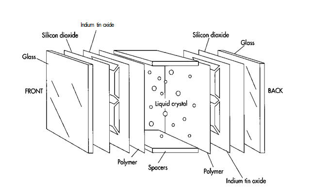
(In all LCDs, the liquid crystal is sandwiched between 2 pieces of glass or transparent plastic called substrates. If glass is used, it is often coated with silicon dioxide to improve liquid crystal alignment. Transparent electrode patterns are then made by applying a layer of indium tin oxide to the glass and using a photolithography or silk screening process to produce the pattern)
The Manufacturing Process
Making passive matrix LCDs is a multi-step process. The surface and rear glass of the display is first polished, washed, and coated with silicon dioxide (S1O2). Next, a layer of indium tin oxide is evaporated onto the glass and etched into the desired pattern. A layer of long chain polymer is then applied to allow the liquid crystals to align properly, followed by a sealing resin. The spacers next are put into place, and the glass sandwich is filled with the liquid crystal material.
Preparing the glass substrates
1 First, the two glass substrates, must be cut to the proper size, polished, and washed. Cutting can be done with a diamond saw or scribe, while polishing involves a process called lapping, in which the glass is held against a rotating wheel that has abrasive particles embedded in it. After being washed and dried, the substrates are coated with a layer of silicon dioxide.
. Making the electrode pattern
2 Next, the transparent electrode pattern must be made on the substrates. This is done by completely coating both front and rear glass surfaces with a very thin layer of indium tin oxide. Manufacturers then make a mask of the desired pattern, using either a silk-screening or photolithography process. They apply the finished mask to the fully coated glass, and areas of indium tin oxide that are not needed are etched away chemically.
3 Alternatively, finer definition can be achieved by using glass that has a layer of etching-resistant, light-sensitive material (called photoresist) above the indium tin oxide film. A mask with the desired pattern is placed over the glass, and the glass is bombarded with ultraviolet light. This light causes the resistive layer it shines on to lose its resistance to etching, allowing the chemicals to eat away both the exposed photoresist and the indium tin oxide below it, thus forming the pattern. The unnecessary photoresist that remains can then be removed with other chemicals. A second variety of resistive film resists etching only after it is exposed to ultraviolet light; in this case, a negative mask of the pattern must be used. Regardless of which method is used, the patterns on the two substrates are designed to overlap only in specific places, a design that ensures that the thin strips of indium tin oxide conveying voltage to each element have no electrode positioned directly opposite that might show up while the cell is working.
Applying the polymer
4 After the electrode pattern is in place, the substrates must be coated with a polymer. The polymer allows the liquid crystals to align properly with the glass surface. Polyvinyl alcohol, polyamides, and some silanes can be used. Polyamides are the most popular agents, because polyvinyl alcohol is subject to moisture problems, and silanes produce a thin, unreliable coating.
5 After coating the glass, manufacturers then stroke the polymer coat in a single direction with soft material. This can result in small parallel grooves being etched into the polymer, or it may simply stretch the polymer coat. In any case, this process forces the liquid crystals to lie parallel to the direction of the stroke. The crystals may be aligned another way, by evaporating silicon oxide onto the glass surface at an oblique angle. This procedure is used to make most digital watch displays but is not convenient for making large-scale displays. It also does not yield the low-tilt angle possible with the previous method.
6 If LCD makers want to align liquid crystals perpendicular to the glass surface, another technique is used: coating the glass with an amphophilic material. This is material whose molecules display affinity for water at one end of the molecule and repulsion from water at the other end. One end— the affinity end—adheres to the glass surface while the other end—the repulsing end—points into the liquid crystal area, repelling the liquid crystals and forming them into an alignment that is perpendicular to the glass surface.
Applying the sealant and injecting the liquid crystal
7 A sealing resin is next applied to the substrates, followed by plastic spacers that will give the liquid crystal cell the proper thickness. Next, the liquid crystal material is injected into the appropriate area between the two glass substrates. The thickness of the LCD cell is usually restricted to 5-25 micrometers. Because proper thickness is crucial for cell operation and because spacers don’t always achieve uniform thickness, LCD makers sometimes put appropriately sized glass fibers or beads in the liquid crystal material. The beads or fibers cannot be seen by the naked eye. They help hold the cell at the proper thickness while the sealant material is setting.
8 To make LCDs more visible, polarizers are added. These are usually made from stretched polyvinyl alcohol films that have iodine in them and that are sandwiched between cellulose acetate layers. Colored polarizers, made using dye instead of iodine, are also available. Manufacturers glue the polarizer to the glass using an acrylic adhesive and cover it with a plastic protective film. They can make reflective polarizers, which also are used in LCDs, by incorporating a simple metal foil reflector.
(In a typical LCD watch assembly, the shaded areas are etched away chemically to form the electrode pattern. The segments are turned on and off individually to either block or allow polarized light to pass through. When electric current is applied to a segment, the light is blocked and a dark spot is created on the reflecting screen.)
Final assembly
9 After the polarizer film is attached, the unit is allowed to age. Finally, the finished glass display assembly is mounted to the circuit boards containing the control and drive electronics. Then, the entire package is ready to be mounted to the device using the LCD—laptop computer, fax machine, clock, etc.
Active Matrix LCD Manu-facture
The process used to make an active matrix LCD (AMLCD) is quite similar to that used for passive matrix LCDs, although it is more complex and more difficult. Generally, the steps of S1O2 coating, indium tin oxide application, and the photoresist etching are replaced by a host of other steps.
In the case of AMLCDs, each LCD component has to be changed to work properly with the thin film transistor and electronics used to boost and clarify the LCD image. Like their passive matrix brethren, active matrix displays are sandwiches consisting of several layers: a polarizing film; a sodium barrier film (S1O2), a glass substrate incorporating a black matrix, and a second sodium barrier film; a color filter and a color filter overcoat made of acrylic/urethane; a transparent electrode; an orientation film made of polyamide; and the actual liquid crystal material incorporating plastic/glass spacers to maintain proper LCD cell thickness.
Quality Control
LCDs—especially those for laptop computer displays—are made under highly controlled conditions in a clean room environment to maximize yield. “Clean rooms” have special air filtering devices designed to keep all dust particles out of the room, and workers inside the room must wear special clothing. Nonetheless, many LCDs have to be discarded because of imperfections. This is particularly true of AMLCDs, which currently have a rejection rate of approximately 50 percent. To minimize the rejection rate, each active device is inspected and as many are repaired as possible. In addition, active matrix assemblies are inspected immediately after the photoresist etching step and again after the liquid crystal material is injected.
The Future
The future is clearly with active matrix LCDs, even though the current rejection rate is very high and the manufacturing process is so expensive. Gradual improvements are expected in the manufacturing process of AMLCDs, and in fact companies are already beginning to offer inspection and repair equipment that may cut the current rejection rate from 50 percent down to around 35 percent.
But the real boost to LCD manufacturing technology may come from all the money that companies are pouring into the research and development process on large screen, AMLCD displays for the long-awaited high definition television technology.
Where To Learn More
Books
Chandrasekhar, S. Liquid Crystals, 2nd ed. Cambridge University Press, 1993.
Collins, Peter J. Liquid Crystals: Nature’s Delicate Phase of Matter. Princeton University Press, 1991.
Doane, J. w., ed. Liquid Crystal Displays and Applications. SPIE-Intemational Society for Optical Engineering, 1990.
Drzaic, p. s., ed. Liquid Crystal Materials, Devices, and Applications. SPIE-International Society for Optical Engineering, 1992.
Kaneko, D. Liquid Crystal TV Displays. Kluwer Academic Publishers, 1987.
O’Mara, William c. Liquid Crystal Flat Panel Display: Manufacturing Science and Technology. Van Nostrand Reinhold, 1993.
Periodicals
Curran, Lawrence. “Kopin, Samoff Team in Advanced LCD Effort.” Electronics. August 10, 1992, p. 11.
Fitzgerald, Michael. “Display Standards Elusive.” Computerworld. December 21, 1992, p. 27.
Fleischmann, Mark. “Wall-Size TV from Tiny LCDs.” Popular Science. June, 1991, p. 94.
Kinnaman, Daniel E. “LCD Panels: The Next Generation.” Technology & Learning. March, 1993, p. 44.
Robinson, Gail M. “Display Systems Leap Forward: New Technologies Offer Designers More Choices Than Ever in CRTs, LCDs, EL and More.” Design News. February 13, 1989, p. 52.
Woodard, Ollie c., Sr. and Tom Long. “Dis¬play Technologies.” Byte. July, 1992, p. 158.