Background
Helicopters are classified as rotary wing aircraft, and their rotary wing is commonly referred to as the main rotor or simply the rotor. Unlike the more common fixed wing aircraft such as a sport biplane or an airliner, the helicopter is capable of direct vertical take-off and landing; it can also hover in a fixed position. These features render it ideal for use where space is limited or where the ability to hover over a precise area is necessary. Currently, helicopters are used to dust crops, apply pesticide, access remote areas for environmental work, deliver supplies to workers on remote maritime oil rigs, take photographs, film movies, rescue people trapped in inaccessible spots, transport accident victims, and put out fires. Moreover, they have numerous intelligence and military applications.
Numerous individuals have contributed to the conception and development of the helicopter. The idea appears to have been bionic in origin, meaning that it derived from an attempt to adapt a natural phenomena—in this case, the whirling, bifurcated fruit of the maple tree—to a mechanical design. Early efforts to imitate maple pods produced the whirligig, a children’s toy popular in China as well as in medieval Europe. During the fifteenth century, Leonardo da Vinci, the renowned Italian painter, sculptor, architect, and engineer, sketched a flying machine that may have been based on the whirligig. The next surviving sketch of a helicopter dates from the early nineteenth century, when British scientist Sir George Cayley drew a twin-rotor aircraft in his notebook. During the early twentieth century, Frenchman Paul Cornu managed to lift himself off the ground for a few seconds in an early helicopter. However, Cornu was constrained by the same problems that would continue to plague all early designers for several decades: no one had yet devised an engine that could generate enough vertical thrust to lift both the helicopter and any significant load (including passengers) off the ground.
Igor Sikorsky, a Russian engineer, built his first helicopter in 1909. When neither this prototype nor its 1910 successor succeeded, Sikorsky decided that he could not build a helicopter without more sophisticated materials and money, so he transferred his attention to aircraft. During World War I, Hungarian engineer Theodore von Karman constructed a helicopter that, when tethered, was able to hover for extended periods. Several years later, Spaniard Juan de la Cierva developed a machine he called an autogiro in response to the tendency of conventional airplanes to lose engine power and crash while landing. If he could design an aircraft in which lift and thrust (forward speed) were separate functions, Cierva speculated, he could circumvent this problem. The autogiro he subsequently invented incorporated features of both the helicopter and the airplane, although it resembled the latter more. The autogiro had a rotor that functioned something like a windmill. Once set in motion by taxiing on the ground, the rotor could generate supplemental lift; however, the autogiro was powered primarily by a conventional airplane engine. To avoid landing problems, the engine could be disconnected and the autogiro brought gently to rest by the rotor, which would gradually cease spinning as the machine reached the ground. Popular during the 1920s and 1930s, autogiros ceased to be produced after the refinement of the conventional helicopter.
The idea for the helicopter appears to have been bionic in origin, meaning that it derived from an attempt to adapt a natural phenomena—in this case, the whirling, bifurcated fruit of the maple tree—to a mechanical design.
The helicopter was eventually perfected by Igor Sikorsky. Advances in aerodynamic theory and building materials had been made since Sikorsky’s initial endeavor, and, in 1939, he lifted off the ground in his first operational helicopter. Two years later, an improved design enabled him to remain aloft for an hour and a half, setting a world record for sustained helicopter flight.
The helicopter was put to military use almost immediately after its introduction. While it was not utilized extensively during World War II, the jungle terrain of both Korea and Vietnam prompted the helicopter’s widespread use during both of those wars, and technological refinements made it a valuable tool during the Persian Gulf War as well. In recent years, however, private industry has probably accounted for the greatest increase in helicopter use, as many companies have begun to transport their executives via helicopter. In addition, helicopter shuttle services have proliferated, particularly along the urban corridor of the American Northeast. Still, among civilians the helicopter remains best known for its medical, rescue, and relief uses.
Design
A helicopter’s power comes from either a piston engine or a gas turbine (recently, the latter has predominated), which moves the rotor shaft, causing the rotor to turn. While a standard plane generates thrust by pushing air behind its wing as it moves forward, the helicopter’s rotor achieves lift by pushing the air beneath it downward as it spins. Lift is proportional to the change in the air’s momentum (its mass times its velocity): the greater the momentum, the greater the lift.
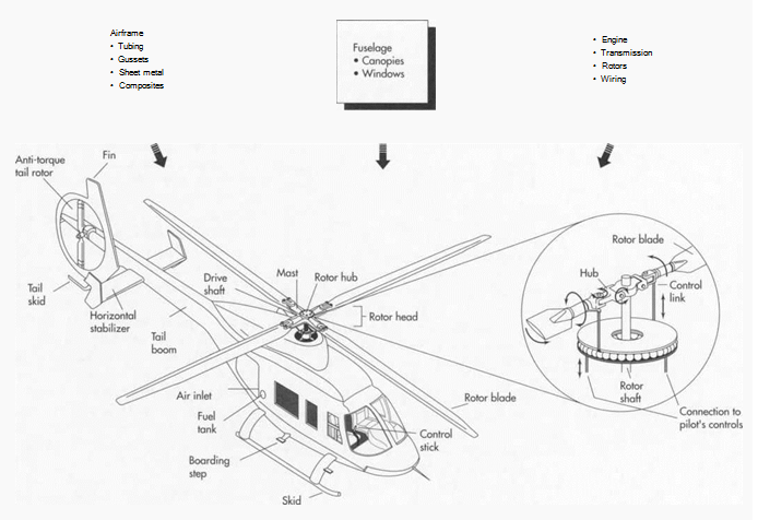
Helicopter rotor systems consist of between two and six blades attached to a central hub. Usually long and narrow, the blades turn relatively slowly, because this minimizes the amount of power necessary to achieve and maintain lift, and also because it makes controlling the vehicle easier. While lightweight, general-purpose helicopters often have a two-bladed main rotor, heavier craft may use a four-blade design or two separate main rotors to accommodate heavy loads.
To steer a helicopter, the pilot must adjust the pitch of the blades, which can be set three ways. In the collective system, the pitch of all the blades attached to the rotor is identical; in the cyclic system, the pitch of each blade is designed to fluctuate as the rotor revolves, and the third system uses a combination of the first two. To move the helicopter in any direction, the pilot moves the lever that adjusts collective pitch and/or the stick that adjusts cyclic pitch; it may also be necessary to increase or reduce speed.
Unlike airplanes, which are designed to minimize bulk and protuberances that would weigh the craft down and impede airflow around it, helicopters have unavoidably high drag. Thus, designers have not utilized the sort of retractable landing gear familiar to people who have watched planes taking off or landing—the aerodynamic gains of such a system would be proportionally insignificant for a helicopter. In general, helicopter landing gear is much simpler than that of airplanes. Whereas the latter require long runways on which to reduce forward velocity, helicopters have to reduce only vertical lift, which they can do by hovering prior to landing. Thus, they don’t even require shock absorbers: their landing gear usually comprises only wheels or skids, or both.
One problem associated with helicopter rotor blades occurs because airflow along the length of each blade differs widely. This means that lift and drag fluctuate for each blade throughout the rotational cycle, thereby exerting an unsteadying influence upon the helicopter. A related problem occurs because, as the helicopter moves forward, the lift beneath the blades that enter the airstream first is high, but that beneath the blades on the opposite side of the rotor is low. The net effect of these problems is to destabilize the helicopter. Typically, the means of compensating for these unpredictable variations in lift and drag is to manufacture flexible blades connected to the rotor by a hinge. This design allows each blade to shift up or down, adjusting to changes in lift and drag.
Torque, another problem associated with the physics of a rotating wing, causes the helicopter fuselage (cabin) to rotate in the opposite direction from the rotor, especially when the helicopter is moving at low speeds or hovering. To offset this reaction, many helicopters use a tail rotor, an exposed blade or ducted fan mounted on the end of the tail boom typically seen on these craft. Another means of counteracting torque entails installing two rotors, attached to the same engine but rotating in opposite directions, while a third, more space-efficient design features twin rotors that are enmeshed, something like an egg beater. Additional alternatives have been researched, and at least one NOTAR (no tail rotor) design has been introduced.
Raw Materials
The airframe, or fundamental structure, of a helicopter can be made of either metal or organic composite materials, or some combination of the two. Higher performance requirements will incline the designer to favor composites with higher strength-to- weight ratio, often epoxy (a resin) reinforced with glass, aramid (a strong, flexible nylon fiber), or carbon fiber. Typically, a composite component consists of many layers of fiber-impregnated resins, bonded to form a smooth panel. Tubular and sheet metal substructures are usually made of aluminum, though stainless steel or titanium are sometimes used in areas subject to higher stress or heat. To facilitate bending during the manufacturing process, the structural tubing is often filled with molten sodium silicate. A helicopter’s rotary wing blades are usually made of fiber-reinforced resin, which may be adhesively bonded with an external sheet metal layer to protect edges. The helicopter’s windscreen and windows are formed of polycarbonate sheeting.
The Manufacturing Process
Airframe: Preparing the tubing
1 Each individual tubular part is cut by a tube cutting machine that can be quickly set to produce different, precise lengths and specified batch quantities. Tubing requiring angular bends is shaped to the proper angle in a bending machine that utilizes inter- changeable tools for different diameters and sizes. For other than minor bends, tubes are fiued with molten sodium silicate that hardens and eliminates kinking by causing the tube to bend as a solid bar. The so-called water glass is then removed by placing the bent tube in boiling water, which melts the inner material. Tubing that must be curved to match fuselage contours is fitted over a stretch forming machine, which stretches the metal to a precisely contoured shape. Next, the tubular details are delivered to the machine shop where they are held in clamps so that their ends can be machined to the required angle and shape. The tubes are then deburred (a process in which any ridges or fins that remain after preliminary machining are ground off) and inspected for cracks.
2 Gussets (reinforcing plates or brackets) and other reinforcing details of metal are machined from plate, angle, or extruded profile stock by routing, shearing, blanking, or sawing. Some critical or complex details may be forged or investment cast. The latter process entails injecting wax or an alloy with a low melting point into a mold or die. When the template has been formed, it is dipped in molten metal as many times as necessary to achieve the thickness desired. When the part has dried, it is heated so that the wax or alloy will melt and can be poured out. Heated to a higher temperature to purify it and placed in a mold box where it is supported by sand, the mold is then ready to shape molten metal into reinforcement parts. After removal and cooling, these parts are then finish-machined by standard methods before being deburred once again.
3 The tubes are chemically cleaned, fitted into a subassembly fixture, and MIG (metal-arc inert gas) welded. In this process, a small electrode wire is fed through a welding torch, and an inert, shielding gas (usually argon or helium) is passed through a nozzle around it; the tubes are joined by the melting of the wire. After welding, the subassembly is stress relieved—heated to a low temperature so that the metal can recover any elasticity it has lost during the shaping process. Finally, the welds are inspected for flaws.
Forming sheet metal details
4 Sheet metal, which makes up other parts of the airframe, is first cut into blanks (pieces cut to predetermined size in preparation for subsequent work) by abrasive water- jet, blanking dies, or routing. Aluminum blanks are heat-treated to anneal them (give them a uniform, strain-free structure that will increase their malleability). The blanks are then refrigerated until they are placed in dies where they will be pressed into the proper shape. After forming, the sheet metal details are aged to full strength and trimmed by routing to final shape and size.
5 Sheet metal parts are cleaned before being assembled by riveting or adhesive bonding. Aluminum parts and welded subassemblies may be anodized (treated to thicken the protective oxide film on the surface of the aluminum), which increases corrosion resistance. All metal parts are chemically cleaned and primer-painted, and most receive finish paint by spraying with epoxy or other durable coating.
Making the cores of composite components
6 Cores, the central parts of the composite components, are made of Nomex (a brand of aramid produced by Du Pont) or aluminum “honeycomb,” which is cut to size by band- saw or reciprocating knife. If necessary, the cores then have their edges trimmed and beveled by a machine tool similar to a pizza cutter or meat slicing blade. The material with which each component is built up from its cores (each component may use multiple cores) is called pre-preg ply. The plies are layers of oriented fibers, usually epoxy or polyimide, that have been impregnated with resin. Following written instructions from the designers, workers create highly contoured skin panels by setting individual plies on bond mold tools and sandwiching cores between additional plies as directed.
7 Completed lay ups, as the layers of pre -preg affixed to the mold are called, are then transported to an autoclave for curing. An autoclave is a machine that laminates plastics by exposing them to pressurized steam, and “curing” is the hardening that occurs as the resin layers “cook” in the autoclave.
8 Visible trim lines are molded into the panels by scribe lines present in the bond mold tools. Excess material around the edges is then removed by band sawing. Large panels may be trimmed by an abrasive water jet manipulated by a robot. After inspection, trimmed panels and other composite details are cleaned and painted by nor-mal spray methods. Surfaces must be well sealed by paint to prevent metal corrosion or water absorption.
Making the fuselage
9 Canopies or windscreens and passenger compartment windows are generally made of polycarbonate sheet. Front panels subject to bird strike or other impact may be laminated of two sheets for greater thickness. All such parts are made by placing an oversized blank on a fixture, heating it, and then forming it to the required curvature by use of air pressure in a free blowing process. In this method, no tool surface touches the optical surfaces to cause defects.
(Most of the crucial components in a helicopter are made of metal and are formed using the usual metal- forming processes: shearing, blanking, forging, cutting, routing, and investment casting. The polycarbonate windscreen and windows are made by laying the sheet over a mold, heating it, and forming it with air pressure in a process called “free blowing,” in which no tool ever touches the part)
Installing the engine, transmission, and rotors
Modem helicopter engines are turbine rather than piston type and are purchased from an engine supplier. The helicopter manufacturer may purchase or produce the transmission assembly, which transfers power to the rotor assembly. Transmission cases are made of aluminum or magnesium alloy.
1 1 As with the above, the main and tail rotor assemblies are machined from specially selected high-strength metals but are produced by typical machine shop methods. The rotor blades themselves are machined from composite layup shapes. Main rotor blades may have a sheet metal layer adhesively bonded to protect the leading edges.
Systems and controls
Wiring harnesses are produced by laying out the required wires on special boards that serve as templates to define the length and path to connectors. Looms, or knitted protective covers, are placed on the wire bundles, and the purchased connectors are soldered in place by hand. Hydraulic tubing is either hand-cut to length and hand- formed by craftsmen, or measured, formed, and cut by tube-bending machines. Ends are flared, and tubes are inspected for dimensional accuracy and to ensure that no cracks are present. Hydraulic pumps and actuators, instrumentation, and electrical devices are typically purchased to specification rather than produced by the helicopter manufacturer.
Final assembly
12 Finished and inspected detail airframe I O parts, including sheet metal, tubular, and machined and welded items, are delivered to subassembly jigs (fixtures that clamp parts being assembled). Central parts are located in each jig, and associated details are either bolted in place or, where rivets are to be used, match-drilled using pneumatically powered drills to drill and ream each rivet hole. For aerodynamic smoothness on sheet metal or composite skin panels, holes are countersunk so that the heads of flat-headed screws won’t protrude. All holes are deburred and rivets applied. A sealant is often applied in each rivet hole as the rivet is inserted. For some situations, semi-auto-mated machines may be used for moving from one hole location to the next, drilling, reaming, sealing, and installing the rivets under operator control.
After each subassembly is accepted byan inspector, it typically moves to another jig to be further combined with other small subassemblies and details such as brackets. Inspected “top level” subassemblies are then delivered to final assembly jigs, where the overall helicopter structure is integrated. Upon completion of the structure, the propulsion components are added, and wiring and hydraulics are installed and tested. Canopy, windows, doors, instruments, and interior elements are then added to complete the vehicle. Finish-painting and trimming are completed at appropriate points during this process.
1 /T After all systems are inspected in final I form, along with physical assemblies and appearance aspects, the complete documentation of materials, processes, inspection, and rework effort for each vehicle is checked and filed for reference. The helicopter propulsion system is tested, and the aircraft is flight-tested.
Quality Control
Once tubular components have been formed, they are inspected for cracks. To find defects, workers treat the tubes with a fluorescent liquid penetrant that seeps into cracks and other surface flaws. After wiping off the excess fluid, they dust the coated tube with a fine powder that interacts with the penetrant to render defects visible. After the tubular components have been welded, they are inspected using X-ray and/or fluorescent penetrant methods to discover flaws. Upon completion, the contours of sheet metal details are checked against form templates and hand-worked as required to fit. After they have been autoclaved and trimmed, composite panels are ultrasonically inspected to identify any possible breaks in laminations or gas-filled voids that could lead to structural failure. Prior to installation, both the engine and the transmission subassemblies are carefully inspected, and special test equipment, custom-designed for each application, is used to examine the wiring systems. All of the other components are also tested before assembly, and the completed aircraft is flight-tested in addition to receiving an overall inspection.
The Future
Manufacturing processes and techniques will continue to change in response to the need to reduce costs and the introduction of new materials. Automation may further improve quality (and lower labor costs). Computers will become more important in improving designs, implementing design changes, and reducing the amount of paperwork created, used, and stored for each helicopter built. Furthermore, the use of robots to wind filament, wrap tape, and place fiber will permit fuselage structures to be made of fewer, more integrated pieces. In terms of materials, advanced, high-strength thermoplastic resins promise greater impact resistance and repair ability than current thermosets such as epoxy and polyimide. Metallic composites such as aluminum reinforced with boron fiber, or magnesium reinforced with silicon carbide particles, also promise higher strength-to-weight ratios for critical components such as transmission cases while retaining the heat resistance advantage of metal over organic materials.
Where To Learn More
Books
Basic Helicopter Handbook. IAP Inc., 1988.
Seddon, J. Basic Helicopter Aerodynamics. American Institute of Aeronautics & Astronautics, 1990.
Periodicals
“Rotary-Wing Technology Pursues Fixed- Wing Performance Capabilities.” Aviation Week & Space Technology. January 19, 1987, p. 46.
“Advanced Technology Prompts Réévaluation of Helicopter Design.” Aviation Week & Space Technology. March 9, 1987, p. 252.
Brown, Stuart F. “Tilt-rotor Aircraft.” Popular Science. July, 1987, p. 46.
“Graphite Tools Produce Volume ’Copter Parts.” Design News. February 17,1986, p. 30.
“Researchers Work on Noise Reduction in Helicopters.” Research & Development. Jan¬uary, 1986, p. 55.
Smith, Bruce A. “Helicopter Manufacturers Divided on Development of New Aircraft.” Aviation Week & Space Technology. February 29, 1988, p. 58.