Background
Prior to the development of artificial refrigeration techniques during the 1800s, people utilized a variety of means to chill and preserve foodstuffs. For centuries, ice served as the principal refrigerant. Ironically, the ancient Indians and Egyptians pioneered an ice- making technique that served as the conceptual basis for the first “modem” refrigerators developed during the nineteenth century: evaporation. The relatively quick evaporation of a liquid creates an expanding volume of gas. As water vapor rises, its kinetic energy increases dramatically, in part because the warm vapor is drawing in energy from its surroundings, which are cooled by this process. The Indians and Egyptians took advantage of this phenomenon by placing wide, shallow bowls filled with water outside during the cool nights. As some water quickly evaporated, the remaining water cooled, forming ice. With this method, it was possible to create sizeable chunks of ice that could then be used to cool food.
Using a more primitive means of procuring ice, the ancient Chinese simply transported it from the mountains to cool their food; later, the Greeks and Romans adopted this practice. To preserve the ice itself, people stored it in pits or caves insulated with straw and wood, by which means they could maintain a supply of ice for months. In industrialized nations, ice served as the primary method of chilling food through the nineteenth century, when people inserted blocks of ice in insulated cabinets alongside the food they wished to store. Even today, in many developing nations ice remains the sole available refrigerant.
The first known attempt to develop an artificial refrigerator took place in Scotland at the University of Glasgow. There, in 1748, William Cullen revived the ancient Indian- Egyptian practice of freezing liquid by means of evaporation, although he accelerated the process by boiling ethyl ether into a partial vacuum (ethyl evaporates more quickly than water). Cullen attempted this merely as an experiment, as did American Oliver Evans, who designed another refrigerator in 1805. Evans’s machine, based on a closed cycle of compressed ether, represented the first effort to use simple vapor instead of vaporizing a liquid. While Evans never developed his machine beyond the prototype stage, in 1844 an American doctor named John Gorrie actually built a very similar machine to provide ice for the hospital in which he worked. Gorrie’s machine compressed air that was next cooled with water. The cooled air was then routed into an engine cylinder, and, as it re-expanded, its temperature dropped enough so that ice could be made.
In 1856 another American, Alexander Twinning, began selling a refrigeration machine based on the same vapor-compression principle, and soon after that Australian James Harrison enlarged the American design (meant to be used in individual homes) for the meat-packing and beer-making industries. Three years later, Ferdinand Carre re-fined the basic concept underlying all of these refrigerators when he introduced am¬monia as a coolant. Ammonia represented an advance because it expands more rapidly than water and can thus absorb more heat from its environs. Carre also contributed other innovations. His refrigerator operated by means of a cycle in which a refrigerant vapor (ammonia) was absorbed in a liquid (a mixture of ammonia and water) that was subsequently heated. The heat caused the refrigerant to vaporize, thereby creating a cooling effect (after it vaporized, the refrigerant was condensed so that it could once again be absorbed in the liquid, repeating the cycle). Carre’s machine not only sold extremely well, it also inaugurated modem refrigeration by upgrading Evans’s compression concept and adding a more sophisticated refrigerant. These components remain the basis of most refrigerators used today.
Ammonia itself posed several problems, however. While it served as a very effective coolant, it was both odiferous and poisonous when it leaked, and it quickly disappeared from refrigeration after synthetic alternatives were developed during the 1920s. The best known of these, patented by Du Pont under the name freon, was created by chemically altering the methane molecule, substituting two chlorine and two fluorine atoms for its four hydrogen atoms. The resulting gas (technically, dichlorofluoromethane) was hailed because its low boiling point, surface tension, and viscosity rendered it an ideal— and ostensibly problem-free—refrigerant. Later, in the 1970s, scientists realized that freon posed problems of its own related to the environment (see “Environmental Concerns” section below) and began searching for new agents to use in refrigeration.
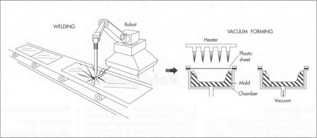
(The outer cabinet and door, made of sheet metal, are either welded or clinched together. While some manufacturers also use sheet metal for the inner cabinet, some manufacturers and some models use plastic for inner liners. The plastic liners are made by vacuum forming. In this process, a thick piece of plastic slightly larger than the finished part has its outer edges clamped and is then heated. The hot plastic is next pulled by vacuum into a mold and cooled. After trimming, the resulting part is ready for assembly)
Raw Materials
Refrigerators today consist of several basic components: the exterior cabinet and door, the inner cabinet or liner, the insulation inserted between the two, the cooling system, the refrigerant, and the fixtures. The cabinet and door are made of aluminum or steel sheet metal that is sometimes prepainted. The metal is generally purchased in a coil that is either fed directly into the manufacturing process or cut to size and fed sheet by sheet. The inner cabinet is made of sheet metal, like the outer cabinet, or of plastic. The insulation that fills the gap between the inner and outer cabinets consists of fiberglass or polyfoam. The components of the cooling system (compressor, condenser, coils, fins) are made of aluminum, copper, or an alloy. The tubing is usually copper, because of that metal’s ductility—its ability to bend without breaking. Freon remains the most commonly used refrigerant, and almost all of the large interior fixtures (door and cabinet liners) are made from vacuum-formed plastic; smaller fixtures (butter compartments, egg trays, salad crispers) are purchased as small plastic blanks or in pre-formed pieces.
Design
The contemporary refrigerator is based on two basic laws of physics: one, that heat flows from warmer material to cooler materials and never the reverse; two, that decreasing the pressure of a gas also decreases its temperature. Although refinements have been made since Carre introduced his model during the late nineteenth century, these basic principles are still visible in today’s refrigerators.
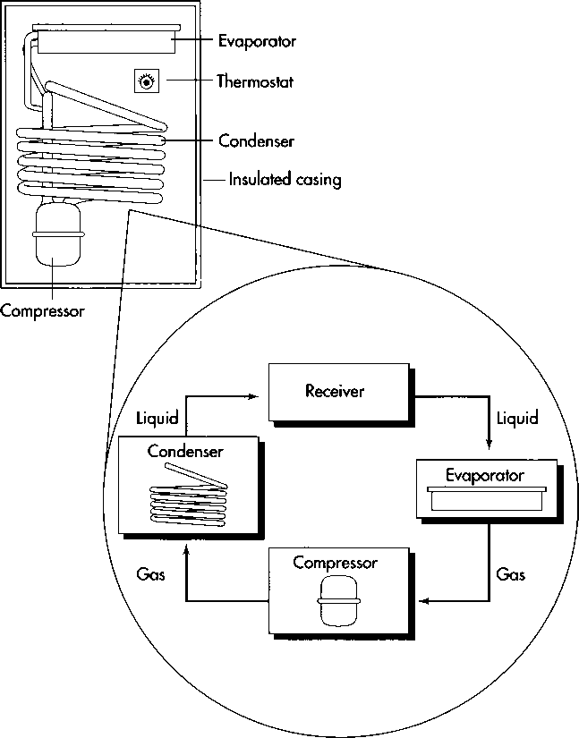
Refrigerators work by removing the warmth from the air within their interior compartments and relaying that heat to the air outside. The coolant (freon) accomplishes this transfer as it passes through a circuit, moving from the evaporator to the condenser. Beginning in the evaporator, which lies inside an insulated cabinet, the freon is heated. Because it has been made to boil, the freon draws heat from the air within the refrigerator. Having absorbed this heat, the freon is then routed to the condenser. In this set of copper coils (usually mounted at the back or on the bottom of the refrigerator), the freon condenses—returns to a liquid state—transferring its heat into the outside air as it does so. After cooling, the freon then returns to the evaporator, where it is once again heated and begins to absorb heat from the food stored within the refrigerator. Sometimes, to increase their surface area (and thus facilitate thermal transfer), the evaporator and the condenser are fitted with metal fins.
For defrosting, a coil is wrapped around the freezer unit. When the timer reaches defrost, the refrigerant is passed through this coil while it is hot to raise the temperature and melt the ice. The coil is generally positioned away from any ice makers to prevent the ice cubes from melting and freezing together.
(A refrigerator works by removing the warmth from the air within its interior compartments and relaying that heat to the air outside. Beginning in the evaporator, the freon is heated and begins to draw heat from the air within the refrigerator. Having absorbed this heat, the freon is then routed to the condenser by the compressor. In this set of copper coils (usually mounted at the back or on the bottom of the refrigerator), the freon returns to a liquid state, transferring its heat into the outside air as it does so. After cooling, the freon returns to the evaporator, where the cycle begins again. )
The Manufacturing Process
Outer cabinet and door
1 Pieces of sheet metal are either welded or clinched together. Clinching is a process closely resembling stapling in that the two pieces are crimped together under pressure, though no additional pieces such as staples are added. If the part of the cabinet is to be visible, it will be welded and ground down to appear as one piece. The extent to which the welding process is automated depends on the company and the number of refrigerators being produced.
2 If the sheet metal was not purchased in precoated form, it is now painted. Some manufacturers use spray equipment to lay a uniform coat of paint on the metal. Others dip the parts in a paint/solvent mixture before heating them to bake the paint onto the surface. ‘
Inner cabinet
3 The inner cabinet is sometimes made from sheet metal very similar to the outer shell. Any seams are caulked to improve insulation and looks. Some manufacturers and some models use plastic for inner liners; for example, the inner door is almost exclusively made from plastic today. The plastic liners are vacuum formed. In this process, a thick piece of plastic slightly larger than the finished part has its outer edges clamped and is then heated. The hot plastic is next pulled by vacuum into a mold and cooled. After trimming, the resulting part is ready for assembly.
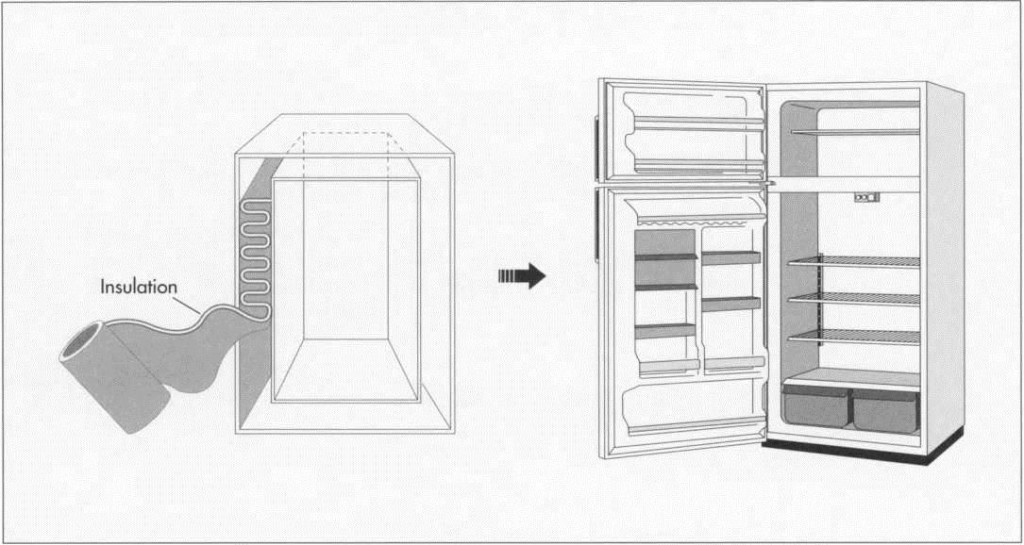
4 The inner cabinet is inserted into the outer cabinet, and the two are snapped together before the fixtures are inserted. Some tubes and wires are run through the gap between the two before it is filled with insulation. A dispensing device (sometimes robotically operated, sometimes a manually operated long ‘gun’) inserts foam between the walls. When heated in an oven, this foam expands to add rigidity and insulation to the cabinet. A similar process is used for the doors.
Cooling system
5 The refrigeration components are attached to the cabinet using screws and clips. The tubing is soldered together, and a protective coating is sprayed on the joints. The order of this assembly varies between manufacturers and models. The copper tubing from which the coils (condensers and evaporators) have separately been cut, bent, and soldered is then attached to the refrigerator as a unit.
6 The seal on the refrigerator door is created by means of magnet laden gaskets that are attached to the doors with screws. Handles and hinges are also screwed onto the door before its hinges are screwed onto the cabinet. Some adjustment is allowed for proper operation of the door.
Testing and adding accessories
7 Most manufacturers mix testing with manufacturing from this point on. The unit is leak tested with nitrogen (a safe gas that makes up about 79 percent of the air); if it passes, it is charged with refrigerant and subjected to further testing. Next, the accessories (shelves, crispers, ice trays, etc.) are added and taped down for shipping. The unit is given a final look and then packaged for shipping.
Quality Control
As mentioned above, all subassemblies of tubing that will contain refrigerant are pressure-tested with nitrogen, which will reveal any flaws in the tubing and in the soldering that joins it. The entire unit is also leak- tested prior to charging with freon. Once charged, the unit is tested as a whole to ensure that it is capable of reaching design temperatures including those necessary during the defrost cycle. The unit is operated with sensors inside that determine the temperature changes over time. Sometimes the refrigerant pressures are also measured. The unit is then subjected to a final ‘sniff test by a machine that detects refrigerant to ensure that no leaks have developed during testing.
By products/Waste
Metal components that are rejected are sold to metal recycling companies. Plastic com¬ponents are ground into small pieces and either reused as raw material or returned to the vendor for reuse. If a unit is rejected after it has been charged, the refrigerant is drained by special equipment and reused.
(The space between the inner and outer cabinets is Filled with foam insulation, usually polystyrene, which can be inserted manually or automatically by a robot. When healed in an oven, this foam expands to add rigidity and insulation to the cabinet. Because this insulation releases CFCs, which contribute to the destruction of the ozone layer, researchers are searching for substitutes. The polystyrene may be replaced by the same kind of vacuum insulation that is used in thermos bottles, since vacuum insulation is more efficient in terms of both space and energy.)
Environmental Concerns
In the mid-1970s, scientists began to understand that as gases in the chlorofluorocarbon (CFC) group, which includes freon, waft upward into the stratosphere (the upper layer of the atmosphere), they gradually decompose, releasing chlorine atoms as they do so. The problem with this is that each chlorine atom can destroy tens of thousands of ozone molecules, ozone being the triatomic form of oxygen that comprises a protective layer in the stratosphere, absorbing much solar ultraviolet radiation that would harm animal life if it reached the earth’s surface. As researchers realized that CFC emissions were exacerbating the hole in the ozone layer over the Antarctic continent, public pressure to limit emissions mounted. In 1987, representatives from nations around the globe signed an agreement, the Montreal Protocol on Substances that Deplete the Ozone Layer, in which they agreed to phase out production of the chemicals known to deplete the ozone layer, including freon. Unfortunately, chlorofluorocarbons are also present in the polystyrene foam that some manufacturers use as an insulator between the external case and the interior lining of their refrigerators. So, efforts to reduce the CFC emissions from refrigerators are presently continuing on two fronts, as manufacturers attempt to find alternatives to both the coolant freon and the insulator polystyrene.
The Future
In terms of freon, several intermediate steps have been taken to minimize CFC emission as researchers attempt to identify safe coolant alternatives. Refrigerator designs have been improved to reduce the amount of freon needed; leak detection systems have been installed; maintenance has been limited to trained, authorized personnel; and refrigerant is recovered and recycled whenever possible. Moreover, long-term replacements for freon are being explored. Thus far, the most promising among them is HCFC-22, which, although still a chlorofluorocarbon, contains an additional hydrogen atom that reduces the molecule’s ozone-depletion capacity by 95 percent. While its cost (three to five times greater than that of freon) is problematic, HCFC-22 is presently undergoing tests to determine its toxicity.
CFC-containing insulation may be replaced by the same kind of vacuum insulation that is used in thermos bottles. Research indicates that vacuum insulation is more efficient in terms of both space and energy, so, at present, it appears that insulation alternatives will become viable well before freon substitutes.
Where To Learn More
Books
Boast, Michael F. Newnes Refrigeration Pocket Book. Butterworth-Heinemann, 1991.
Cerepnalkovski, I. Modern Refrigerating Machines. Elsevier Science Publishing, 1991.
Dellino, Clive V. Cold and Chilled Storage Technology. Van Nostrand Reinhold, 1989.
Marsh, R. Warren and Olive C. Throats. Principles of Refrigeration. Delmar Publishers Inc., 1979.
Stoecker, W. F. and J. W. Jones. Refrigeration & Air Conditioning. McGraw-Hill, 1982.
Periodicals
“Refrigeration’s Revitalization.” Appliance, February 1993, pp. 54-58.
“Refrigerator Doors Have a ‘Clear’ Edge.” Design News. January 7, 1991, p. 33.
“A $30-million Super-Efficient Refrigerator.” Electrical World. July, 1992, p. 30.
Marbach, William D. “Now, An Icebox That’s Cool for the Environment.” Business Week. July 22, 1991, p. 65.
Murray, Charles J. “Plastic Welding Technique Aids Refrigerator Assembly: Special Parts Replace Metal Anchors on Refrigerator Liners.” Design News. February 15, 1988, p. 230.

