Background
An optical fiber is a single, hair-fine filament drawn from molten silica glass. These fibers are replacing metal wire as the transmission medium in high-speed, high-capacity communications systems that convert information into light, which is then transmitted via fiber optic cable. Currently, American telephone companies represent the largest users of fiber optic cables, but the technology is also used for power lines, local access computer networks, and video transmission.
Alexander Graham Bell, the American inventor best known for developing the telephone, first attempted to communicate using light around 1880. However, light wave communication did not become feasible until the mid-twentieth century, when advanced technology provided a transmission source, the laser, and an efficient medium, the optical fiber. The laser was invented in 1960 and, six years later, researchers in England discovered that silica glass fibers would carry light waves without significant attenuation, or loss of signal. In 1970, a new type of laser was developed, and the first optical fibers were produced commercially.
Raw Materials
Optical fibers are composed primarily of silicon dioxide (S1O2), though minute amounts of other chemicals are often added. Highly purified silica powder was used in the now- outmoded crucible manufacturing method, while liquid silicon tetrachloride (SiCU) in a gaseous stream of pure oxygen (O2) is the principal source of silicon for the vapor deposition method currently in widespread use. Other chemical compounds such as germanium tetrachloride (GeCk) and phosphorus oxychloride (POCb) can be used to produce core fibers and outer shells, or claddings, with function-specific optical properties.
Because the purity and chemical composition of the glass used in optical fibers determine the most important characteristic of a fiber— degree of attenuation—research now focuses on developing glasses with the highest possible purity. Glasses with a high fluoride content hold the most promise for improving optical fiber performance because they are transparent to almost the entire range of visible light frequencies. This makes them especially valuable for multimode optical fibers, which can transmit hundreds of discrete light wave signals concurrently.
In a fiber optic communications system, cables made of optical fibers connect data links that contain lasers and light detectors. To transmit information, a data link converts an analog electronic signal—a telephone conversation or the output of a video camera— into digital pulses of laser light. These travel through the optical fiber to another data link, where a light detector reconverts them into an electronic signal.
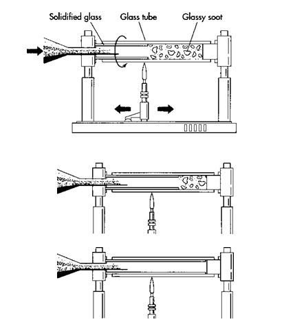
(To make an optical fiber, layers of silicon dioxide are first deposited on the inside surface of a hollow substrate rod. This is done using Modified Chemical Vapor Deposition, in which a gaseous stream of pure oxygen combined with various chemical vapors is applied to the rod. As the gas contacts the hot surface of the rod, a glassy soot several layers thick forms inside the rod. After the soot is built up to the desired thickness, the substrate rod is moved through other heating steps to drive out any moisture and bubbles trapped in the soot layers. During heating, the substrate rod and internal soot layers solidify to form the boule or preform of highly pure silicon dioxide.)
Design
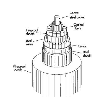
In a fiber optic cable, many individual optical fibers are bound together around a central steel cable or high-strength plastic carrier for support. This core is then covered with protective layers of materials such as aluminum, Kevlar, and polyethylene (the cladding). Because the core and the cladding are constructed of slightly differing materials, light travels through them at different speeds. As a light wave traveling in the fiber core reaches the boundary between the core and cladding, these compositional differences between the two cause the light wave to bend back into the core. Thus, as a pulse of light travels through an optical fiber, it is constantly bouncing away from the cladding. A pulse moves through the optical fiber at the speed of light—186,290 miles per second (299,340 kilometers per second) in a vacuum, somewhat slower in practice—losing energy only because of impurities in the glass and because of energy absorption by irregularities in the glass structure.
Energy losses (attenuation) in an optical fiber are measured in terms of loss (in decibels, a unit of energy) per distance of fiber. Typically, an optical fiber has losses as low as 0.2 decibels per kilometer, meaning that after a certain distance the signal becomes weak and must be strengthened, or repeated. With current datalink technology, laser signal repeaters are necessary about every 30 kilometers (18.5 miles) in a long-distance cable. However, on-going research in optical material purity is aimed at extending the distance between repeaters of an optical fiber up to 100 kilometers (62 miles).
There are two types of optical fibers. In a single-mode fiber, the core is smaller, typically 10 micrometers (a micrometer is one- millionth of a meter) in diameter, and the cladding is 100 micrometers in diameter. A single-mode fiber is used to carry just one light wave over very long distances. Bundles of single-mode optical fibers are used in long-distance telephone lines and undersea cables. Multimode optical fibers, which have a core diameter of 50 micrometers and a cladding diameter of 125 micrometers, can carry hundreds of separate light wave signals over shorter distances. This type of fiber is used in urban systems where many signals must be carried to central switching stations for distribution.
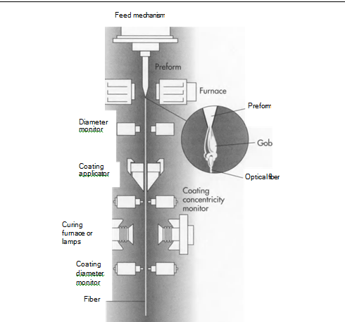
(After the solid glass preform is prepared, it is transferred to a vertical drawing system. In this system, the preform is first heated. As it does so, a gob of molten glass forms at its end and then falls away, allowing the single optical fiber inside to be drawn out. The fiber then proceeds through the machine, where its diameter is checked, a protective coating is applied, and it is cured by heat. Finally, it is wound on a spool.)
The Manufacturing Process
Both the core and the cladding of an optical fiber are made of highly purified silica glass. An optical fiber is manufactured from silicon dioxide by either of two methods. The first, the crucible method, in which powdered silica is melted, produces fatter, multimode fibers suitable for short-distance transmission of many light wave signals. The second, the vapor deposition process, creates a solid cylinder of core and cladding material that is then heated and drawn into a thinner, single mode fiber for long-distance communication.
There are three types of vapor deposition techniques: Outer Vapor Phase Deposition, Vapor Phase Axial Deposition, and Modified Chemical Vapor Deposition (MCVD). This section will focus on the MCVD process, the most common manufacturing technique now in use. MCVD yields a low-loss fiber well- suited for long-distance cables.
Modified Chemical Vapor Deposition
1 First, a cylindrical preform is made by depositing layers of specially formulated silicon dioxide on the inside surface of a hollow substrate rod. The layers are deposited by applying a gaseous stream of pure oxygen to the substrate rod. Various chemical vapors, such as silicon tetrachloride (SiCU), germanium tetrachloride (GeCL), and phosphorous oxychloride (POCL), are added to the stream of oxygen. As the oxygen contacts the hot surface of the rod—a flame underneath the rod keeps the walls of the rod very hot—silicon dioxide of high purity is formed. The result is a glassy soot, several layers thick, deposited inside the rod. This soot will become the core. The properties of these layers of soot can be altered depending on the types of chemical vapors used.
2 After the soot is built up to the desired thickness, the substrate rod is moved through other heating steps to drive out any moisture and bubbles trapped in the soot layers. During heating, the substrate rod and internal soot layers solidify to form the boule or preform of highly pure silicon dioxide. A preform usually measures 10 to 25 millimeters (.39 to .98 inch) in diameter and 600 to 1000 millimeters (23.6 to 39.37 inches) in length.
(A typical optical fiber cable usually includes several optical fibers around a central steel cable. Various protective layers are applied, depending on the harshness of the environment where the cable will be situated)
Drawing the fibers
3 The solid preform is then automatically transferred to a vertical fiber drawing system. The machines that make up a typical vertical drawing system can be two stories high and are able to produce continuous fibers up to 300 kilometers (186 miles) long. This system consists of a furnace to melt the end of the preform, sensors to monitor the diameter of the fiber being pulled from the preform, and coating devices to apply protective layers over the outer cladding.
4 The preform first passes through a furnace, where it is heated to about 3600 degrees Fahrenheit (about 2000 degrees Celsius). Next, a drop of molten glass called a “gob” forms at the end of the preform, much like a droplet of water that collects at the bottom of a leaky faucet. The gob then falls -‘ctway, and the single optical fiber inside is drawn out of the preform. As the optical fiber is pulled from the preform, the material in the original substrate rod forms the cladding, and the silicon dioxide deposited as soot forms the core of the optical fiber.
5 As the fiber is drawn out, measuring devices monitor its diameter and its concentricity, while another device applies a protective coating. The fiber then passes through a curing furnace and another measuring device that monitors diameter, before being wound on a spool.
Quality Control
Quality control begins with the suppliers of the chemical compounds used as the raw materials for the substrate rods, chemical reactants, and fiber coatings. Specialty chemical suppliers provide detailed chemical analyses of the constituent compounds, and these analyses are constantly checked by computerized on-stream analyzers connected to the process vessels.
Process engineers and highly trained technicians closely watch the sealed vessels as preforms are being created and fibers drawn. Computers operate the complex control schemes necessary to manage the high temperatures and high pressures of the manufacturing process. Precise measurement devices continuously monitor fiber diameter and provide feedback for control of the drawing process.
The Future
Future optical fibers will come from ongoing research into materials with improved optical properties. Currently, silica glasses with a high fluoride content hold the most promise for optical fibers, with attenuation losses even lower than today’s highly efficient fibers. Experimental fibers, drawn from glass containing 50 to 60 percent zirconium fluoride (ZrFi), now show losses in the range of 0.005 to 0.008 decibels per kilometer, whereas earlier fibers often had losses of 0.2 decibels per kilometer.
In addition to utilizing more refined materials, the producers of fiber optic cables are experimenting with process improvement. Presently, the most sophisticated manufacturing processes use high-energy lasers to melt the preforms for the fiber draw. Fibers can be drawn from a preform at the rate of 10 to 20 meters (32.8 to 65.6 feet) per second, and single-mode fibers from 2 to 25 kilometers (1.2 to 15.5 miles) in length can be drawn from one preform. At least one company has reported creating fibers of 160 kilometers (99 miles), and the frequency with which fiber optics companies are currently retooling—as often as every eighteen months—suggests that still greater innovations lie ahead. These advances will be driven in part by the growing use of optical fibers in computer net-works, and also by the increasing demand for the technology in burgeoning international markets such as Eastern Europe, South America, and the Far East.
Where To Learn More
Books
Yeh, Chai. Handbook of Fiber Optics. Academic Press, 1990.
Periodicals
Jungbluth, Eugene D. “How Do They Make Those Marvelous Fibers?” Laser Focus World. March, 1992, p. 165.
Ketron, Lisa A. “Fiber Optics: The Ultimate Communications Media.” Ceramic Bulletin. Volume 66, number 11, 1987, p. 1571.
Shuford, Richard S. “An Introduction to Fiber Optics,” Byte. December, 1984, p. 121.
Soja, Thomas A. “Worldwide Telecom Demand Spurs Fiber Optics Market.” Laser Focus World. December, 1992, p. 83.
Wire Journal International. October, 1992 (entire issue devoted to fiber optics).

