Background
Missiles differ from rockets by virtue of a guidance system that steers them towards a pre-selected target. Unguided, or free-flight, rockets proved to be useful yet frequently inaccurate weapons when fired from aircraft during the World War II. This inaccuracy, often resulting in the need to fire many rockets to hit a single target, led to the search for a means to guide the rocket towards its target. The concurrent explosion of radio-wave technology (such as radar and radio detection devices) provided the first solution to this problem. Several warring nations, including the United States, Germany and Great Britain, mated existing rocket technology with new radio- or radar-based guidance systems to create the world’s first guided missiles. Although these missiles were not deployed in large enough numbers to radically divert the course of the World War II, the successes that were recorded with them pointed out techniques that would change the course of future wars. Thus dawned the era of high-technology warfare, an era that would quickly demonstrate its problems as well as its promise.
The problems centered on the unreliability of the new radio-wave technologies. The missiles were not able to hone in on targets smaller than factories, bridges, or warships. Circuits often proved fickle and would not function at all under adverse weather conditions. Another flaw emerged as jamming technologies flourished in response to the success of radar. Enemy jamming stations found it increasingly easy to intercept the radio or radar transmissions from launching aircraft, thereby allowing these stations to send conflicting signals on the same frequency, jamming or “confusing” the missile. Battlefield applications for guided missiles, especially those that envisioned attacks on smaller targets, required a more reliable guidance method that was less vulnerable to jamming. Fortunately, this method became available as a result of an independent research effort into the effects of light amplification.
Dr. Theodore Maiman built the first laser (Light Amplification by Stimulated Emission of Radiation) at Hughes Research Laboratories in 1960. The military realized the potential applications for lasers almost as soon as their first beams cut through the air. Laser guided projectiles underwent their baptism of fire in the extended series of air raids that highlighted the American effort in the Vietnam War. The accuracy of these weapons earned them the well-known sobriquet of “smart weapons.” But even this new generation of advanced weaponry could not bring victory to U.S. forces in this bitter and costly war. However, the combination of experience gained in Vietnam, refinements in laser technology, and similar advances in electronics and computers, led to more sophisticated and deadly laser guided missiles. They finally received widespread use in Operation Desert Storm, where their accuracy and reliability played a crucial role in the decisive defeat of Iraq’s military forces. Thus, the laser guided missile has established itself as a key component in today’s high-tech military technology.
Raw Materials
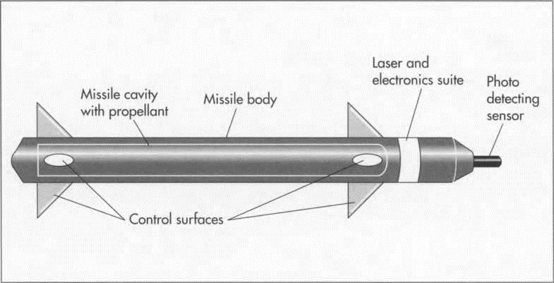
A laser guided missile consists of four important components, each of which contains different raw materials. These four components are the missile body, the guidance system (also called the laser and electronics suite), the propellant, and the warhead. The missile body is made from steel alloys or high- strength aluminum alloys that are often coated with chromium along the cavity of the body in order to protect against the excessive pressures and heat that accompany a missile launch. The guidance system contains various types of materials—some basic, others high-tech—that are designed to give maximum guidance capabilities. These materials include a photo detecting sensor and optical filters, with which the missile can interpret laser wavelengths sent from a parent aircraft. The photo detecting sensor’s most important part is its sensing dome, which can be made of glass, quartz, and/or silicon. A missile’s electronics suite can contain gallium-arsenide semiconductors, but some suites still rely exclusively on copper or silver wiring. Guided missiles use nitrogen-based solid propellants as their fuel source. Certain additives (such as graphite or nitroglycerine) can be included to alter the performance of the propellant. The missile’s warhead can contain highly explosive nitrogen-based mixtures, fuel-air explosives (FAE), or phosphorous compounds. The warhead is typically encased in steel, but aluminum alloys are sometimes used as a substitute.
(The missile body is die-cast in halves: molten metal (either aluminum or steel) is poured into a metal die and cooled to form the proper shape. The two halves are then welded together. The principal laser components— the photo detecting sensor and optical filters—are assembled in a series of operations that are separate from the rest of the missile’s construction. Circuits that support the laser system are then soldered onto pre-printed boards. The circuit boards for the electronics suite are also assembled independently from the rest of the missile. If called for by the design, microchips are added to the boards at this time.)
Design
Two basic types of laser guided missiles exist on the modern battlefield. The first type “reads” the laser light emitted from the launching aircraft/helicopter. The missile’s electronic suite issues commands to the fins (called control surfaces) on its body in an effort to keep it on course with the laser beam. This type of missile is called a beam rider as it tends to ride the laser beam towards its target.
The second type of missile uses on-board sensors to pick up laser light reflected from the target. The aircraft/helicopter pilot selects a target, hits the target with a laser beam shot from a target designator, and then launches the missile. The missile’s sensor measures the error between its flight path and the path of the reflected light. Correction messages are then passed on to the missile’s control surfaces via the electronics suite, steering the missile onto its target.
Regardless of type, the missile designer must run computer simulations as the first step of the design process. These simulations assist the designer in choosing the proper laser type, body length, nozzle configurations, cavity size, warhead type, propellant mass, and control surfaces. The designer then puts together a package containing all relevant engineering calculations, including those generated by computer simulations. The electronics suite is then designed around the capabilities of the laser and control surfaces. Drawings and schematics of all components can now be completed; CAD/CAM (Computer-Aided Design/Manufacture) technology has proven helpful with this task. Electronics systems are then designed around the capabilities of the aircraft’s laser and the missile’s control surfaces. The following step consists of generating the necessary schematic drawings for the chosen electronics system. Another computer-assisted study of the total guided missile system constitutes the final step of the design process.
The Manufacturing Process
Constructing the body and attaching the fins
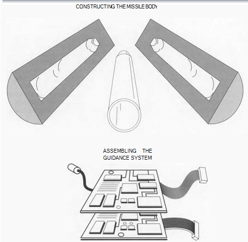
1 The steel or aluminum body is die cast in halves. Die casting involves pouring molten metal into a steel die of the desired shape and letting the metal harden. As it cools, the metal assumes the same shape as the die. At this time, an optional chromium coating can be applied to the interior surfaces of the halves that correspond to a completed missile’s cavity. The halves are then welded together, and nozzles are added at the tail end of the body after it has been welded.
2 Moveable fins are now added at predetermined points along the missile body. The fins can be attached to mechanical joints that are then welded to the outside of the body, or they can be inserted into recesses purposely milled into the body.
Casting the propellant
3 The propellant must be carefully applied to the missile cavity in order to ensure a uniform coating, as any irregularities will result in an unreliable burning rate, which in turn detracts from the performance of the missile. The best means of achieving a uniform coating is to apply the propellant by using centrifugal force. This application, called casting, is done in an industrial centrifuge that is well-shielded and situated in an isolated location as a precaution against fire or explosion.
Assembling the guidance system
4 The principal laser components—the photo detecting sensor and optical filters—are assembled in a series of operations that are separate from the rest of the missile’s construction. Circuits that support the laser system are then soldered onto pre-printed boards; extra attention is given to optical materials at this time to protect them from excessive heat, as this can alter the wavelength of light that the missile will be able to detect. The assembled laser subsystem is now set aside pending final assembly. The circuit boards for the electronics suite are also assembled independently from the rest of the missile. If called for by the design, microchips are added to the boards at this time.
5 The guidance system (laser components plus the electronics suite) can now be integrated by linking the requisite circuit boards and inserting the entire assembly into the missile body through an access panel. The missile’s control surfaces are then linked with the guidance system by a series of relay wires, also entered into the missile body via access panels. The photo detecting sensor and its housing, however, are added at this point only for beam riding missiles, in which case the housing is carefully bolted to the exterior diameter of the missile near its rear, facing backward to interpret the laser signals from the parent aircraft.
Final assembly
6 Insertion of the warhead constitutes the final assembly phase of guided missile construction. Great care must be exercised during this process, as mistakes can lead to catastrophic accidents. Simple fastening techniques such as bolting or riveting serve to attach the warhead without risking safety hazards. For guidance systems that home-in on reflected laser light, the photo detecting sensor (in its housing) is bolted into place at the tip of the warhead. On completion of this final phase of assembly, the manufacturer has successfully constructed on of the most complicated, sophisticated, and potentially dangerous pieces of hardware in use today.
(Current laser guided missiles work in one of two ways. The first type, a “beam rider,” reads the laser light emitted from the launching aircraft and rides the beam toward the target. The second type uses on-board sensors to pick up laser light sent by the aircraft and reflected from the target. The sensors measure the error between the missile’s flight path and the path of the reflected light, and the electronics suite alters the control surfaces as necessary to guide the missile toward the target.)
Quality Control
Each important component is subjected to rigorous quality control tests prior to assembly. First, the propellant must pass a test in which examiners ignite a sample of the propellant under conditions simulating the flight of a missile. The next test is a wind tunnel exercise involving a model of the missile body. This test evaluates the air flow around the missile during its flight. Additionally, a few missiles set aside for test purposes are fired to test flight characteristics. Further work involves putting the electronics suite through a series of tests to determine the speed and accuracy with which commands get passed along to the missile’s control surfaces. Then the laser components are tested for reliability, and a test beam is fired to allow examiners to record the photo detecting sensor’s ability to “read” the proper wavelength. Finally, a set number of completed guided missiles are test fired from aircraft or helicopters on ranges studded with practice targets.
Byproducts/Waste
Propellants and explosives used in warheads are toxic if introduced into water supplies. Residual amounts of these materials must be collected and taken to a designated disposal site for burning. Each state maintains its own policy pertaining to the disposal of explosives, and Federal regulations require that disposal sites be inspected periodically. Effluents (liquid byproducts) from the chromium coating process can also be hazardous. This problem is best dealt with by storing the effluents in leak-proof containers. As an additional safety precaution, all personnel involved in handling any hazardous wastes should be given protective clothing that includes breathing devices, gloves, boots and overalls.
The Future
Future laser guided missile systems will carry their own miniaturized laser on board, doing away with the need for target designator lasers on aircraft. These missiles, currently under development in several countries, are called “fire-and-forget” because a pilot can fire one of these missiles and forget about it, relying on the missile’s internal laser and detecting sensor to guide it towards its target. A further development of this trend will result in missiles that can select and attack targets on their own. Once their potential has been realized, the battlefields of the world will feel the deadly venom of these “brilliant missiles” for years to come. An even more advanced concept envisions a battle rifle for infantry that also fires small, laser guided missiles. Operation Desert Storm clearly showed the need for laser guided accuracy, and, as a result, military establishments dedicated to their missions will undoubtedly invent and deploy ever more lethal versions of laser guided missiles.
Where To Learn More
Books
Bova, Ben. The Beauty of Light. John Wiley and Sons, 1988.
Hallmark, Clayton L. and Delton T. Horn. Lasers: The Light Fantastic. TAB Books, 1987.
Hecht, Jeff. Optics: Light for a New Age. Charles Scribner’s Sons, 1987.
Iannini, Robert. E. Build Your Own Fiberoptic, Infrared, and Laser Space-Age Projects. TAB Books, 1987.
Laurence, Clifford L. The Laser Book: A New Technology of Light. Prentice Hall, 1986.
Von Braun, Wernher, Frederick I. Ordway
III, and Dave Dooling. Space Travel: A History. Harper & Row, 1985.
Wood, Derek. Jane’s World Aircraft Recognition Handbook. Jane’s Information Group, 1989.
Wulforst, Harry. The Rocketmakers. Orion Books, 1990.
Periodicals
“A Dull Scalpel for the Surgical Strike on Libya.” Discover. June, 1986, p. 8.
Lenorowitz, Jeffrey M. “F-l 17s Drop Laser- Guided Bombs in Destroying Most Baghdad Targets.” Aviation Week and Space Technology. Feb. 4, 1991, p. 30.
Magnusson, Paul. “American Smart Bombs, Foreign Brains.” Business Week. March 4, 1991, p. 18.

