Background
The lawn mower is a mechanical device that literally shaves the surface of the grass by using a rapidly rotating blade or blades.
For centuries, grass was cut by workers who walked through pastures or fields wielding small, sharp scythes. In addition to being tiring and slow, manual cutting was ineffective—the scythes worked well only when the grass was wet. The first mechanical grass- cutting device appeared in 1830, when an English textile worker named Edwin Budding developed a mower allegedly based on a textile machine used to shear the nap off of cloth. Budding’s cylindrical mower was attached to a rear roller that propelled it with a chain drive, and it shaved grass with a curved cutting edge attached to the cylinder. He created two sizes, large and small. The large mower had to be drawn by horses, whose hooves were temporarily shod with rubber boots to prevent them from damaging the turf; the head gardener at the London Zoo was among the first to purchase this model. Budding marketed the smaller mower to country gentlemen, who would, he claimed, “find in [his] machine an amusing, useful and healthful exercise.”
Mechanized grass cutting was evidently slow to catch on, perhaps because Budding’s mower was quite heavy in addition to being inefficiently geared. Only two lawn mower manufacturers exhibited their machines at England’s Great Exhibition in 1851. However, several decades later the new machines experienced a surge in popularity due to the interest in lawn tennis that arose in England during the late Victorian period. Before the turn of the century, Budding’s initial designs were improved. Weighing considerably less than their predecessors and based on the side wheel design still used in today’s most popular mowers, these refined machines were soon visible in yards throughout England.
The earliest gas-driven lawn mowers were designed in 1897 by the Benz Company of Germany and the Coldwell Lawn Mower Company of New York. Two years later an English company developed its own model; however, none of these companies mass produced their designs. In 1902 the first commercially produced power mower, designed by James Edward Ransome, was manufactured and sold. Although Ransome’s mower featured a passenger seat, most early mowers did not, and even today the most popular models are pushed from behind.
Power mowers are presently available in four basic designs: the rotary mower, the power reel mower, the riding mower, and the tractor. Because the rotary mower is by far the most common, it is the focus of this entry. Pushed from behind, rotary mowers feature a single rotating blade enclosed in a case and supported by wheels. As the engine turns, it spins the blade. The blade whirls at 3,000 revolutions per minute, virtually 19,000 feet (5,800 meters) per minute at the tip of the blade where the cutting actually occurs. The best rotaries feature a horn of plenty (cornucopia) or wind tunnel shape curving around the front of the housing and ending at the discharge chute through which the mown grass flies out. Self-propelled models are driven by a chain or belt connected to the engine’s drive shaft. A gearbox usually turns a horizontal axle which in turn rotates the wheels. Some models have a big chain- or belt-driven movable unit that rises up off and settles down on the wheels. The power reel mower features several blades attached at both ends to drums that are attached to wheels. The coupled engine drive shaft that spins the reel can also be rigged to propel the mower, if desired. Overlapping the grass, this machine’s five to seven blades pull it against a cutting bar at the bottom of the mower. Then one or more rollers smooth and compact the clippings as the mower goes over them. Reel mowers are more efficient than rotary mowers because the latter actually use only the end of the blade to do most of the cutting, whereas the fixed blades in a reel mower cut with the entire length of both edges. However, rotary mowers are easier to manufacture because the basic design is simpler, and they are also favored over reel mowers on most types of turf. By industry estimates, most of the 40 million mowers in use on any given summer Saturday are rotary mowers.
Raw Materials
The typical gas-powered walk-behind mower may have as many as 270 individual parts, including a technologically advanced two- or four-cycle engine, a variety of machined and formed parts, various subassemblies purchased from outside contractors, and many pieces of standard hardware. Most of these pieces are metal, including the major components: mower pan, handlebar, engine, and blades. A few, however, are made of plastic, such as side discharge chutes, covers, and plugs.
The Manufacturing Process
Manufacturing the conventional rotary lawn mower requires precision inventory control, strategic placement of parts and personnel, and synchronization of people and tasks. In some instances, robotic cells are used in conjunction with a trained labor force.
Unloading and distributing the components
Trucked into the plant’s loading dock, the components are moved by forklifts or overhead trolleys to other centers for forming, machining, painting, or, if they require no additional work upon arrival, assembly. Lawn mower components arrive at factory to areas for assembly.
Mower pan is machine stamped with pressure.
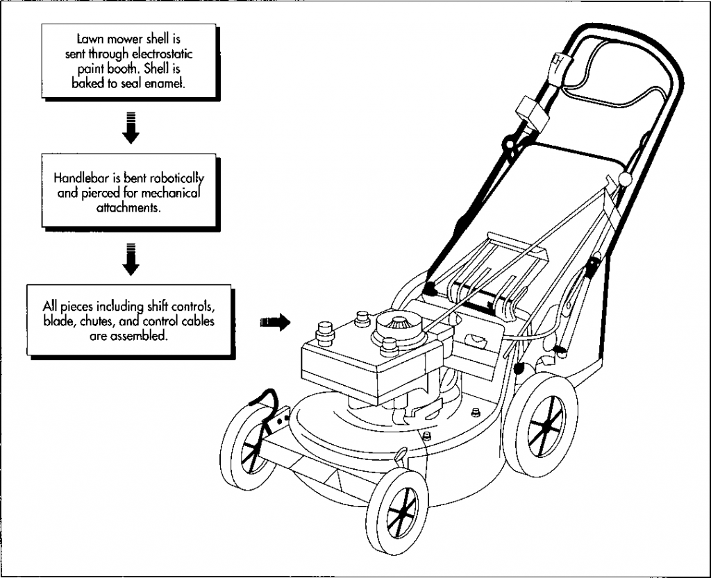
2 The steel mower pan, the largest single part and one used in various models, is first machine-stamped under great heat and pressure. The pan is then transported to a robotic cell, where a plasma cutter creates apertures in it. The term plasma refers to any of a number of gases (argon is commonly used) that can be raised to high temperature and highly ionized by being passed through a constricted electrical arc. When directed through the narrow opening of a torch, this hot, ionized gas can be used for both cutting and welding.
3 After other elements such as baffles (deflecting plates) are welded on, the finished pan and a number of other exposed parts are powder painted in a sealed room. Powder painting entails thoroughly washing the parts in alkaline and phosphate solutions and rinsing them to seal the surfaces. The parts are then attached to overhead conveyors and run through a paint booth. Fine paint particles are sprayed from a gun that imbues them with an electrostatic charge—opposite to the charge given to the part being painted—that causes the paint to adhere to the surface of the parts evenly. Next, the parts are baked in ovens to produce a permanently fixed, enamel-like coating. The pan and other parts are now ready to withstand years of exposure to corrosive grass fluids and the constant peppering from dirt and debris kicked up in the cutting process.
(The shell is painted electrostatically and then baked to seal the paint. Meanwhile, the handelbar is bent and pierced by robots, and then the remaining components are assembled)
Shaping the handlebar
4 The handlebar is created in a robotic cell whose mechanical arms perform three operations. In a bender, the tubing is first bent in at least four places. A second press operation flattens the ends, and a third pierces fourteen or so round and square holes in the tubing. These holes will accommodate the starting mechanism, blade and wheel drive control, and the pan attachment. The finished handlebar is then transported to a subassembly station, where many of the controls are added.
Other subassemblies
5 The other major subassemblies are also created at various plant centers using formed, machined, or purchased materials and standard hardware. Parts purchased from outside suppliers include engines built to manufacturer’s physical and performance specifications, tires, shift mechanisms, wiring harnesses, and bearings. Injection- molded plastic parts are purchased for use in side discharge chutes, covers, and plugs. Injection molding refers to a process in which molten plastic is squirted into a mold and then allowed to cool. As it cools, the plastic assumes the shape of the mold.
6 Assembly teams put the six or more major subassemblies together on a rolling line at a pace determined by the task and skills required. The engine is first placed upside down in a frame fixture, and the mower pan is bolted down along with the drive mechanism. Then come the rear axle, brackets, and rods to secure the shift controls. The blade and accompanying clutch wheels and parts are fastened to the engine through the pan opening with preset air-driven torque wrenches. After another team member adds hardware and wheels, the unit is flipped onto its wheels. The handlebar is attached, and control cables are secured and set. Finally, the mower—each mower—is performance- tested before shipment to dealers, where some final set-up adjustments are made.
Quality Control
Inspectors monitor the manufacturing process throughout the production run, checking fits, seams, tolerances, and finishes. In particular, the paint operation is scrutinized. Samples of each painted part are regularly pulled off the line for ultrasonic testing, a process that utilizes the corrosion activity created in a salt bath to simulate 450 hours of continuous exposure to the natural environment. Painted parts are also scribed and the deterioration of the exposed surface watched for tell-tale signs of rust. If needed, the paint or cleaning cycles are adjusted to assure high quality and durable finishes.
Final performance testing—the last step in the assembly sequence—guarantees reliability and safety for users. A small quantity of a gas/oil mixture is added to each engine. A technician cranks the engine and checks its rpm with a gauge; drive elements and safety switches are also checked. As required by current Consumer Product Safety Commission regulations, the mower blade, when running, must stop within three seconds after the control handle is released.
The Future
Like many other machines, the lawn mower will benefit from the development of new and more efficient power sources. A recent invention is the solar-powered lawn mower, which uses energy from the sun rather than gasoline as fuel. It needs no tune ups or oil changes, and it operates very quietly. Perhaps its biggest drawback is the amount of energy its battery can store: only enough for two hours of cutting, which must be followed by three days of charging. However, as batteries with more storage capabilities are developed, this drawback will disappear.
Where To Learn More
Books
Davidson, Homer L. Care and Repair of Lawn and Garden Tools. TAB Books, 1992.
Hall, Walter. Parp’s Guide to Garden and Power Tools. Rodale Press, 1983.
Nunn, Richard. Lawn Mowers and Garden Equipment. Creative Homeowner Press, 1984.
Peterson, F. Handbook of Lawn Mower Repair. Putnam, 1984.
Periodicals
Buderi, Robert. “Now, You Can Mow the Lawn from Your Hammock.” Business Week. May 14,1990, p. 64.
“Robo-Mower.” The Futurist. January-Feb- ruary, 1989, p. 39.
Kimber, Robert. “Pushing toward Safety: The Evolution of Lawn-Mower Design.” Horticulture. May, 1990, p. 70.
Murray, Charles J. “Riding Mower’s Design Reduces Turning Radius.” Design News. April 5, 1993, p. 81.
Smith, Emily T. “A Lawn Mower That Gets Its Power from the Sun.” Business Week. February 11, 1991, p. 80.

